Care of Series-Parallel Filament Circuits: Part 2
This note applies to directly heated tubes and their circuits only.
Concept
Directly heated receiving and low power transmitting tubes - aka "Battery Tubes" - usually have direct low voltage heaters such as 1.5V (E:D), 2V (E:K) or 3V which were designed to be supplied directly by battery voltages (e.g. 1.5V carbon/zinc). In consumer receivers, the heaters of all tubes were often wired in parallel - supplied by a single 1.5V filament battery cell. This arrangement does however not prove convenient, should the radio be powered from a vehicle, aircraft, by mains power or should the filament voltage or current need to be regulated. Enters the series connection of the filaments in the radio, supplied through a series resistor (or better a "baretter" = current regulator) to make up the nominal supply voltage, as found e.g. in the Zenith "Transoceanics" or military radios like the AN/VRC-8/9/10 and many others.
In order for this concept to work, the filament circuit branches need to be balanced so that the current and voltage for each tube (and dial-lamp) is correct for their rating. Often additional parallel/series resistors are needed to balance out the cathode current of the directly heated tubes and possible differences in filament requirements. Often this filament circuit is shown separately on the circuit diagram, also indicating current regulators, balancing resistors, RF bypass capacitors or RF chokes. The diagram below is a good example, showing 5 paralleled series strings plus mixing battery tubes with a standard 6.3V indirectly heated tube (note the 6AK5 in the lower left corner).
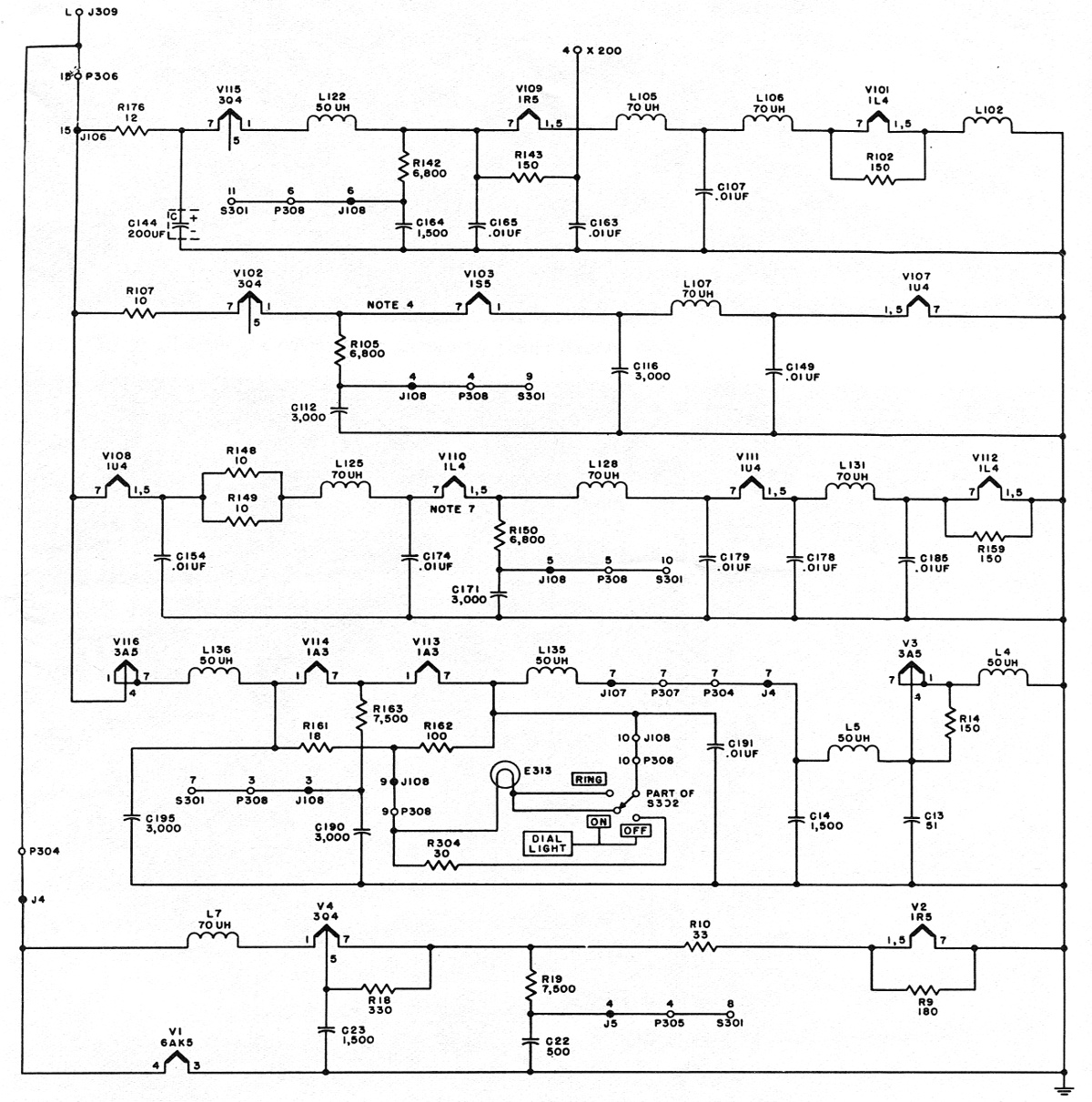
Example design: RT-66/67/68, receiver section
Replacement and Substitution
To maintain the designed balance, all tubes and dial-lamps need to be replaced by exact or truly equivalent types. Thus the e.g. the use of LEDs as dial lamps or the modification of audio output stages using transistors or ICs to save battery power should be considered carefully.
Failure Scenarios
If a current regulator (baretter) supplies several branches in parallel, care needs to be taken that all branches are working - otherwise the current will be directed to the working part only - increasing the heater voltages in the remaining branches to provoke further tube failures. The solution to this problem is to either add a shunt regulator after the baretter to limit the maximum voltage or replace the baretter by a voltage regulator - with suitable cold-start current limiting - to supply a regulated heater voltage (rather than current) - a tube failure will in both cases no longer change the current through any other tubes and cause snow-balling failures.