My Display at the VCFE CH 18 in Zurich
After showing a working PDP8/E system, the new display was planned to be quite different. Back in the late 70ies/early 80ies a lot of people were building their own microcomputers, assembled kits and wrote assembler programs to enter the new area of personal computing. My own start was to resurrect a PDP8-S and build kits, a Heathkit H9 video terminal and a H10 paper tape reader-punch. INTERSIL offered the SAMPLER 6960 as a kit (kit picture here) based on the IM6100 "PDP8 on a chip" family. The kit was then built and tested - that was all. While the PDP8-S now resides in a museum, the other components were still carefully stored. So this would be the basis of my new display!
The next question of course was, what could be demonstrated live with this configuration? There are just 256 words of RAM memory on the board, but also ODT-F in a ROM providing some useful functions. And there is, apart from the serial terminal I/O, a parallel 12bit I/O interface! The first idea was to punch tapes with readable letters from the terminal, but this known program needs more memory space. So something simpler but attractive had to be controlled. As I have quite a bit of Marklin model railway, this was the new "process". Now restoration and design work could be started.
,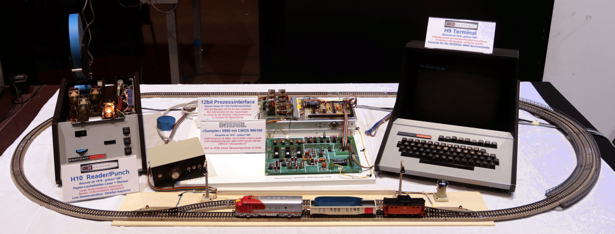
The complete IM6100 family controlled railway display, ready to go - it all had to fit on 2m of table space. Click on picture to enlarge.
The INTERSIL 6960 Sampler and the Process Control Hardware
The existing sampler board, with all options installed, was checked out and ODT-F found to be working. Note: I built two boards and they both have the same quirky problem: after boot you need to go to single step, reset and advance some 50 steps, then let it run. However once it runs, no further errors are produced. Despite only a 2MHz clock and after changing chips etc. I was unable to find the source of this difficulty. Then a few things were added to make it more user-friendly. These included new screw terminals, a DC-DC converter to supply the negative voltage, a battery back-up for the memory bank and a change to the clock generator circuit for the UART to allow 1200Bd on RS-232 rather than 110Bd only.
The next step was designing the process interface logic. The 12bit word was defined to have 8bits for the speed control and the remaining 4bits for control signals (points, light and bell). A manual control box contains 4 switches and a potentiometer, the latter is providing a voltage to an ADC which reads it every 80ms. The switches are buffered and the 12bits wired to the 6960. The speed output is converted by a DAC and buffered with a power amplifier to drive the loco. Two outputs are buffered and wired to relays and the remaining two outputs are fed to one-shot chips to provide 1s pulses via relays to the point coils (the Marklin points have two coils, one for each direction and require a pulse to set them).
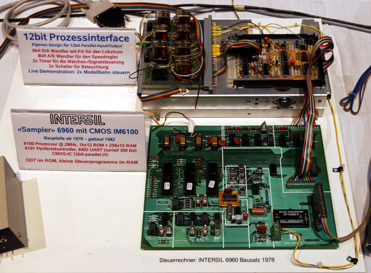
The 6960 Sampler Board below and the Process Control Interface above
The Heathkit H9 and H10 Peripherals
The video terminal needed some work, the keys did not always make contact and the display, after coming up nicely, sometimes got into a "wobbling" mode. The keys cannot be removed or opened but after exercising them, things started improving and finally errors were rare. For the display problem the power supply and the deflection circuits were tested and some capacitors replaced. The source of the problem was never really found, but in the end it went away. A bit unsatisfactory really, but everything worked during the show.
The paper tape reader-punch was fantastic: all it needed was a bit of teletype oil in the punch die and it worked as it always did. As it was not connected to the microcomputer system, the copy mode was used to demonstrate the punching of tapes and the cover removed so the visitors could see the mechanical action of the big magnets in the unit - made quite an impression.
Software
Two small assembler routines were programmed using PAL8 on the Win8 emulation. The first one takes input from the manual control box (speed, lights, points, bell) and controls the output relays and D/A converter while displaying the parallel output word on the terminal. The second routine allows to control the speed of the train by inputs on the keyboard terminal and displays the current setting. To save memory locations the terminal is serviced by routines in the ODT-F ROM which were designed to be also used by user programs. The programs were entered and started using ODT-F, both have CTRL-C to return to ODT-F. Here are the listings of both programs